Smart Energy Surveillance
Background and Problem Statement
IT is a backbone of all industry verticals and it has expanded to solve number of challenges in very scalable, efficient and automated way. Energy Savings is one of such cause, particularly energy is consumed by mankind is growing exponentially year after year. Smart Energy management is the key topic of any Smart City Initiative. Government of India and State Govt of Gujarat has taken number of initiatives including renewable energy solutions based on Solar and Wind, however there is immediate opportunity to effectively MONITOR and MANAGE the existing consumption of Energy, such as large industries, Government building.
While India is embarking it’s journey on 100 top Smart Cities, It is essential that Safety and Security of our mission critical infrastructure like Power infrastructure of key Govt Building.
Also, as a security measures and to address any unfortunate events , it is essential that key Govt building remain operationalize and uninterruptable power is essential. Even in case of any mechanical or electrical failure, it is essential that power should be restored as soon as possible.
Solution
Addressing various parameters (Energy savings, Secure and Uninterruptable power), as highlighted above, Cilans systems has proposed and deployed a cutting edge IOT Solution that is custom built based on the field proven technologies and state of art products.
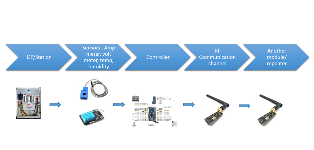
POC for the Solution was built using widely deployed and field proven microcontrollers and sensors (to measure voltage , current, temperature) that are integrated using RF technologies. RF was used to develop independent wireless communication network, as in highly secure Govt building, any 3rd party solution won’t be allowed to use their existing wi-fi netwok for security reasons. We had developed our own wireless communication intra-floor and inter-floors to cover various Distribution boards across the building. As as Architecture diagram, each module represents a placement within each Distribution Panel (where we will be measuring live voltage and current for all three phases ). These is called transmitter modules, which are powered from live supply and also battery protected. In the case of power failure, it will switch over to battery power instantaneously.
All reading will be communicated and channelized to downward floor and eventually all data is collected at fixed internals (Default : 15 seconds but configurable as needed) and will be collected at receiver module designed to accumulate all results and send to connected server. Server will be recording all data and based on power condition (On or Off). System will alert the respective electrical technicians and respective authorities (through SMS)
Typical distance between any of the module won’t exceed 25 to 30 meters. Solution will be measuring reading from each DB (Distribution Board). Typically 4 will be placed on every floor and all accumulated results will be channelized to Control Room, where all reading will be known to receiver dashboard.
Features and Benefits
- Instant notifications to respective technicians about power loss anywhere, 24x7
- Robust and field proven solution
- All intrer-module communication is archived without tapping into existing wireless infrastructure.
- Solution is always on and can handle power failure using state of art power switching circuitry to battery backup
- Daily data can be used to take corrective action (for example, in the night time, if current utilization is detected on particular section of building then it could be due to some AC is left ON by mistake)
- Historic data can used to measure energy consumption trends and for capacity planning.


